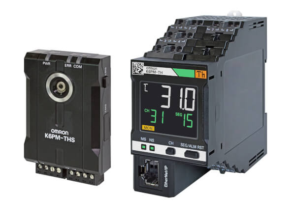
K6PM-TH
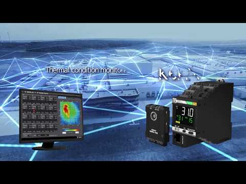
Monitorização do estado com base em termografia
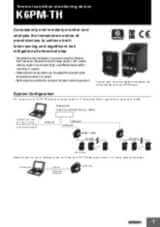
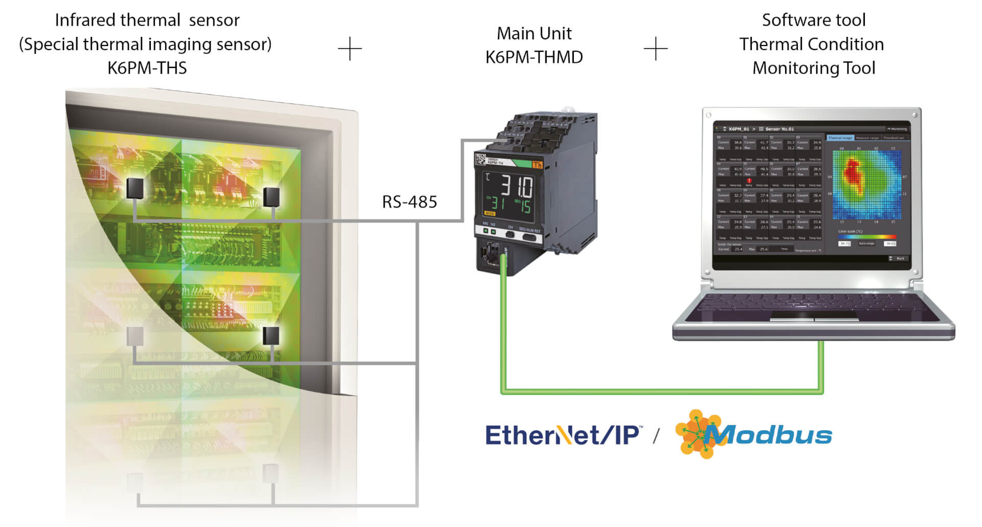
O K6PM-TH mede e monitoriza a temperatura da superfície através de até 31 câmaras de infravermelhos ligadas, como uma termografia contínua.
- Monitorizar e prever a tendência da temperatura, ativando o alarme sempre que a temperatura de uma determinada área estiver acima do limite definido, ou caso se espere que esta atinja um valor crítico num futuro próximo
- Considerar a tendência diferencial de temperatura (entre o ambiente e o objeto medido), ativando alarmes apenas se se verificarem condições críticas.
- Definir automaticamente o limite de temperatura de cada área (cada câmara divide a área monitorizada em 16 quadrantes), com base nas condições da linha de base
- notificações por e-mail em caso de aviso/alarme;
- monitorização remota;
- interação com aplicações personalizadas e com o servidor MQTT.
Especificações e info encomendas
| Produto | Supply voltage AC | Supply voltage DC | Descrição | |
|---|---|---|---|---|
|
|
20.4-26.4 V | 20.4-26.4 V | Dispositivo de monitorización del estado térmico para armarios de control y cuadros, 24 V CC, salida de control de transistor, Push-In Plus, pantalla LCD, EtherNet/IP y Modbus TCP |
|
Precisa de ajuda?
Estamos aqui para ajudar! Contacte-nos e os nossos especialistas irão ajudá-lo a encontrar a melhor solução para a sua empresa.
Contactar K6PM-TH

Obrigado por ter feito o seu pedido. Entraremos em contacto consigo logo que possível.
Temos experienciado dificuldades técnicas. O seu pedido não foi submetido com sucesso. Por favor aceite as nossas desculpas e tente novamente mais tarde. Detalhes: [details]
Orçamento para K6PM-TH
Através deste formulário pode pedir um orçamento para o produto que escolheu. Por favor complete os campos marcados com *. Os seus dados serão tratados confidencialmente.
Obrigado por ter pedido uma cotação. Enviaremos a respectiva informação logo que possível.
Temos experienciado dificuldades técnicas. O seu pedido não foi submetido com sucesso. Por favor aceite as nossas desculpas e tente novamente mais tarde. Detalhes: [details]
Feature
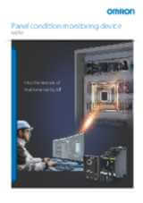
O K6PM é um parceiro fiável para monitorizar painéis críticos das instalações, bem como painéis de equipamento ao longo de toda a respetiva vida útil (desenvolvimento, validação, FAT e após a instalação).
Particularmente adequado para aplicações em que o painel está localizado junto a uma máquina que gera calor intenso (fornalhas, fornos, máquinas de moldagem).
Os dispositivos de monitorização do estado podem ser configurados com uma única ferramenta
Configuração fácil em três passos. A ferramenta de configuração da monitorização do estado permite a configuração em lote de uma vasta gama de dispositivos de monitorização do estado, como os utilizados para monitorizar motores, temperaturas, isolamentos e aquecedores. Pode ser utilizada sem quaisquer competências especiais, reduzindo a necessidade de formação
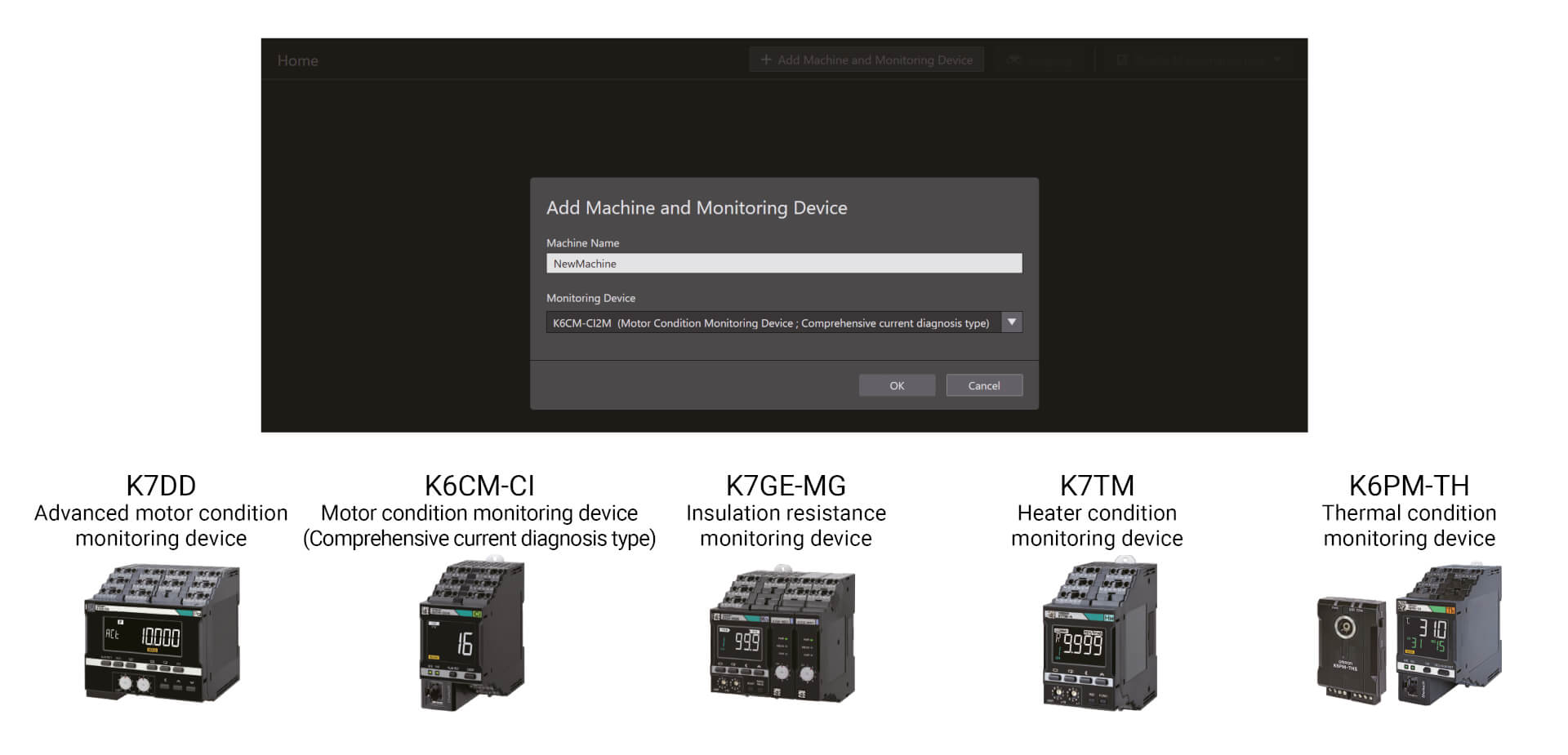
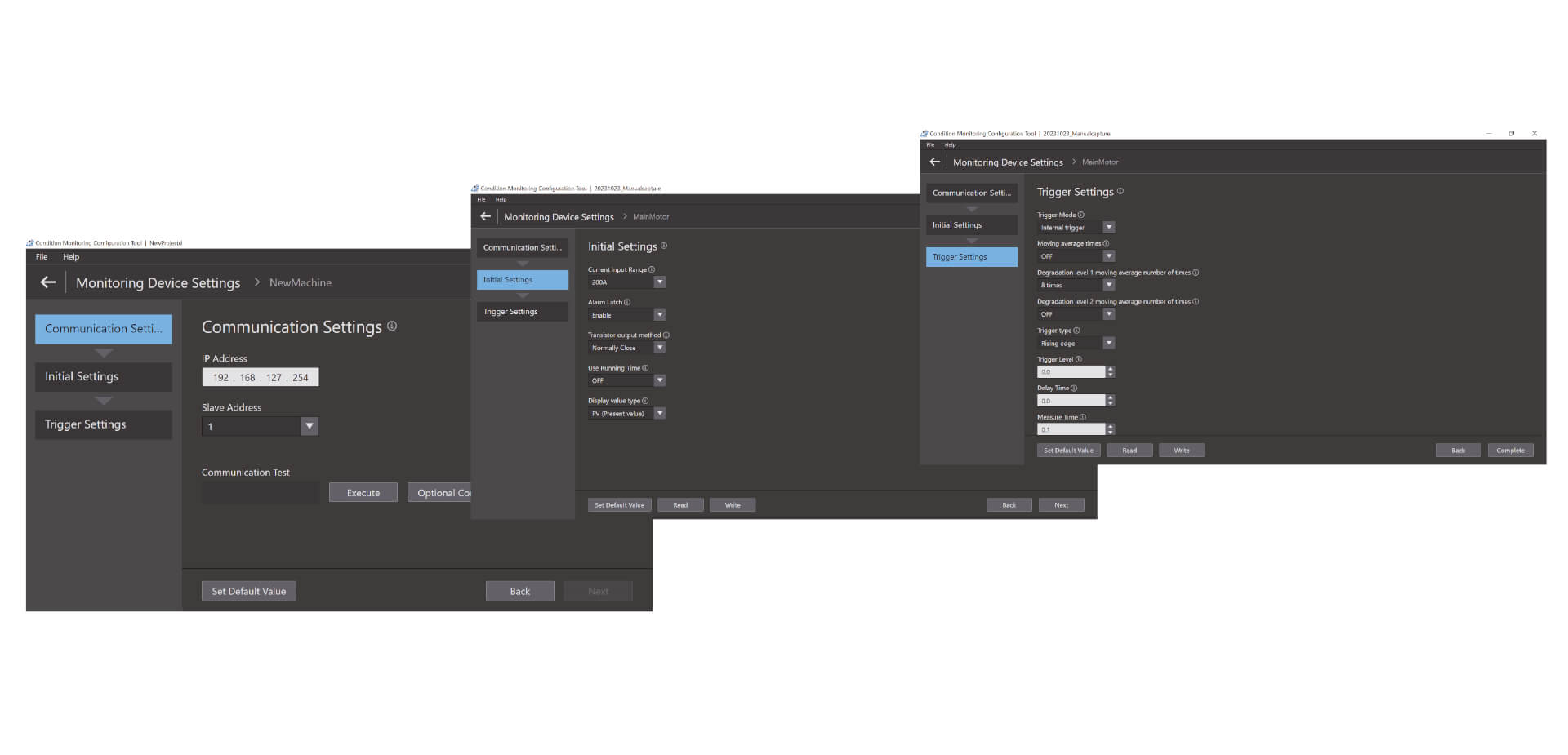
Configuração fácil em três passos
A ferramenta de configuração da monitorização do estado permite a configuração em lote de uma vasta gama de dispositivos de monitorização do estado, como os utilizados para monitorizar motores, temperaturas, isolamentos e aquecedores. Pode ser utilizada sem quaisquer competências especiais, reduzindo a necessidade de formação. A configuração é efetuada em apenas três passos: configuração das comunicações, configuração inicial e configuração do acionador. *1 Com a sua elevada operacionalidade, a ferramenta aumenta também a produtividade no local.
Vídeos
-
OMRON K6PM-TH Thermal Condition Monitor Detecting Dryer Duct Leak
Coating and drying is one of the most dangerous processes in car manufacturing. In the drying oven, air heated to 400°C in the combustion chamber travels through the air duct for use in drying. These air ducts degrade over time, sometimes allowing air hotter than 100°C to leak, which can lead to burn injuries during patrol inspection. #omronindustrialautomation #MakeitOMRON
02:59
OMRON K6PM-TH Thermal Condition Monitor Detecting Dryer Duct Leak
Coating and drying is one of the most dangerous processes in car manufacturing. In the drying oven, air heated to 400°C in the combustion chamber travels through the air duct for use in drying. These air ducts degrade over time, sometimes allowing air hotter than 100°C to leak, which can lead to burn injuries during patrol inspection. #omronindustrialautomation #MakeitOMRON
-
K6PM: Innovation in thermal monitoring and panel maintenance
Parts to check are increasing as devices and wires in a panel increase for high-functioned facilities and equipment. On the other hand, maintenance frequency is decreasing due to shortage of the maintenance engineers, resulting in a higher risk of accident. There are various causes of failures on the device. Current methods of manual inspections are useful but they only provide limited amount of failure detection information. Here is a new solution from OMRON.
02:37
K6PM: Innovation in thermal monitoring and panel maintenance
Parts to check are increasing as devices and wires in a panel increase for high-functioned facilities and equipment. On the other hand, maintenance frequency is decreasing due to shortage of the maintenance engineers, resulting in a higher risk of accident. There are various causes of failures on the device. Current methods of manual inspections are useful but they only provide limited amount of failure detection information. Here is a new solution from OMRON.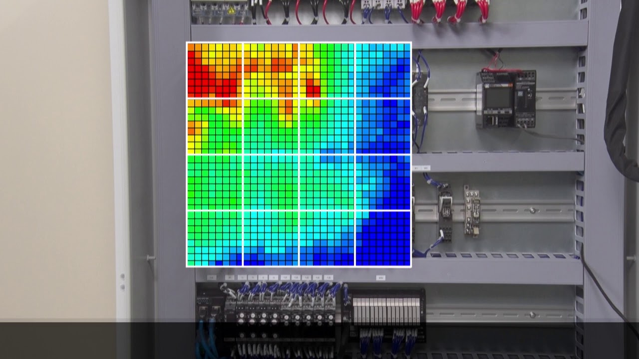
-

Omron K6PM "Auto threshold set" algorithm
The amount of heat generated varies from device to device. For this reason, the optimum threshold value for the thermal monitoring must be set depending on the device. K6PM can divide one sensor monitoring area into 16 segments and automatically set the threshold for each segment.
01:27
Omron K6PM "Auto threshold set" algorithm
The amount of heat generated varies from device to device. For this reason, the optimum threshold value for the thermal monitoring must be set depending on the device. K6PM can divide one sensor monitoring area into 16 segments and automatically set the threshold for each segment.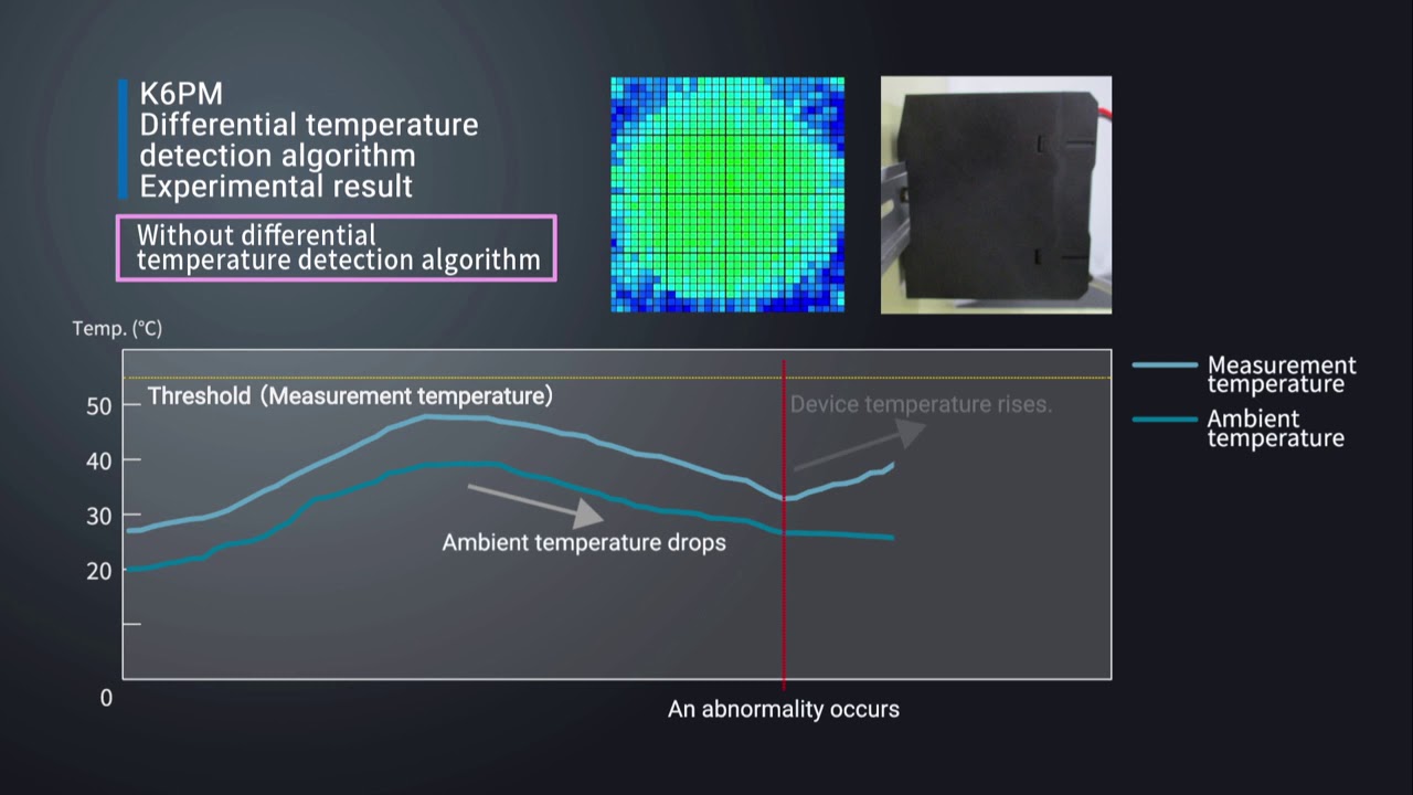
-

Omron K6PM "Differential temperature detection" algorithm
For applications where there are fluctuations in ambient temperature, it can be difficult to determine the cause of the temperature change of the device. The K6PM constantly monitors the difference between measure temperature and ambient temperature. This allows the K6PM to accurately detect abnormalities without being affected by ambient temperatures.
01:51
Omron K6PM "Differential temperature detection" algorithm
For applications where there are fluctuations in ambient temperature, it can be difficult to determine the cause of the temperature change of the device. The K6PM constantly monitors the difference between measure temperature and ambient temperature. This allows the K6PM to accurately detect abnormalities without being affected by ambient temperatures.
-

Omron K6PM "Arrival prediction" algorithm
Predicts the estimated temperature value based on the temperature rise trend. With the Predictive temperature algorythm, you can quickly identify potential risks before they ccould lead failures and machine downtime. Watch a testing example.
01:52
Omron K6PM "Arrival prediction" algorithm
Predicts the estimated temperature value based on the temperature rise trend. With the Predictive temperature algorythm, you can quickly identify potential risks before they ccould lead failures and machine downtime. Watch a testing example.
-

Installation procedure of thermal image sensor (K6PM-THS) in the panel
Watch the installation video for a smooth integration of the K6PM.
02:33
Installation procedure of thermal image sensor (K6PM-THS) in the panel
Watch the installation video for a smooth integration of the K6PM.Produtos
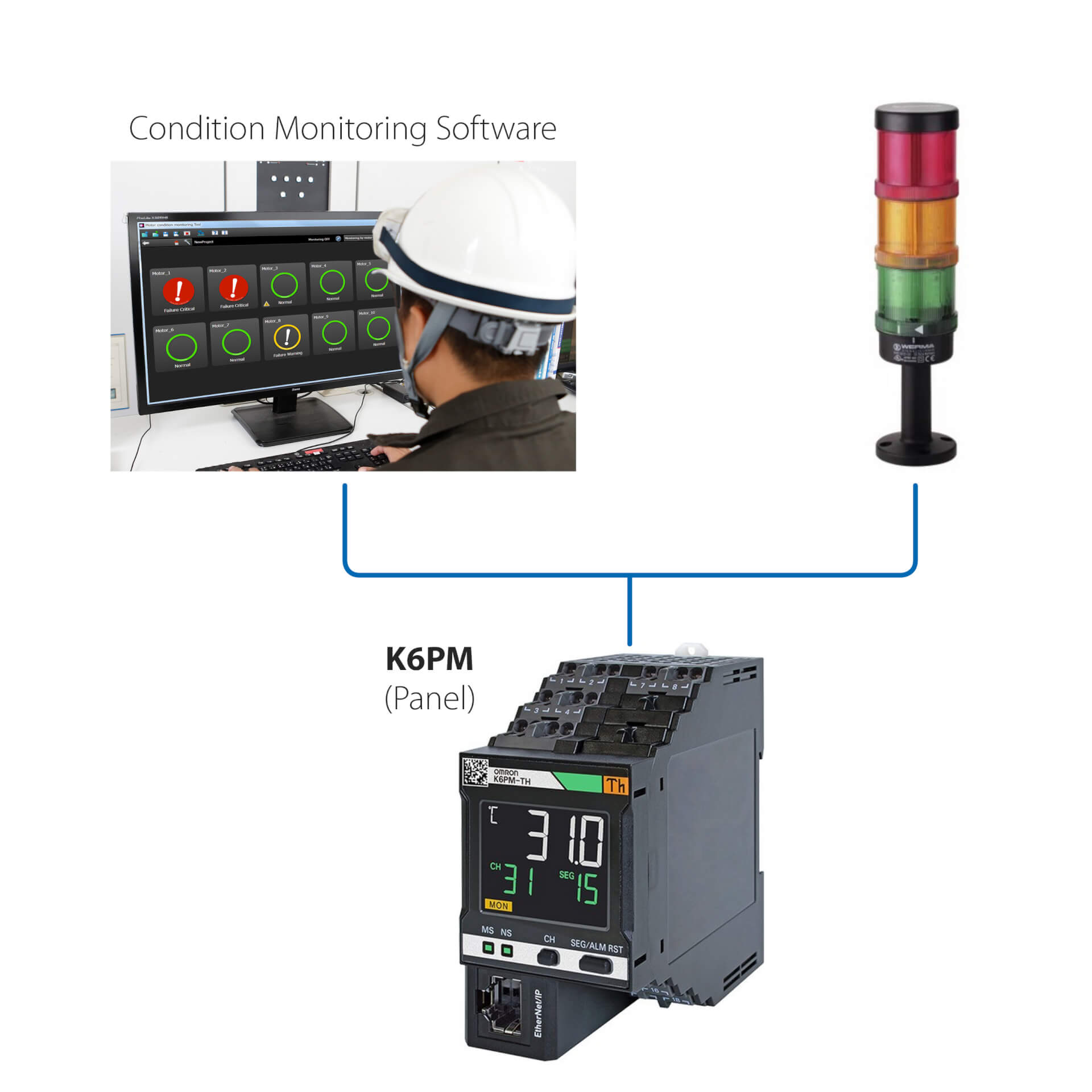
Instalação autónoma (sem PLC)
Esta solução simples permite:
- Monitorizar o estado do motor através do LED integrado ou do software de monitorização do estado
- Configurar os controladores através do software de monitorização do estado fornecido com o dispositivo
- Ligar o K6PM a quaisquer dispositivos de E/S externos (saída digital)
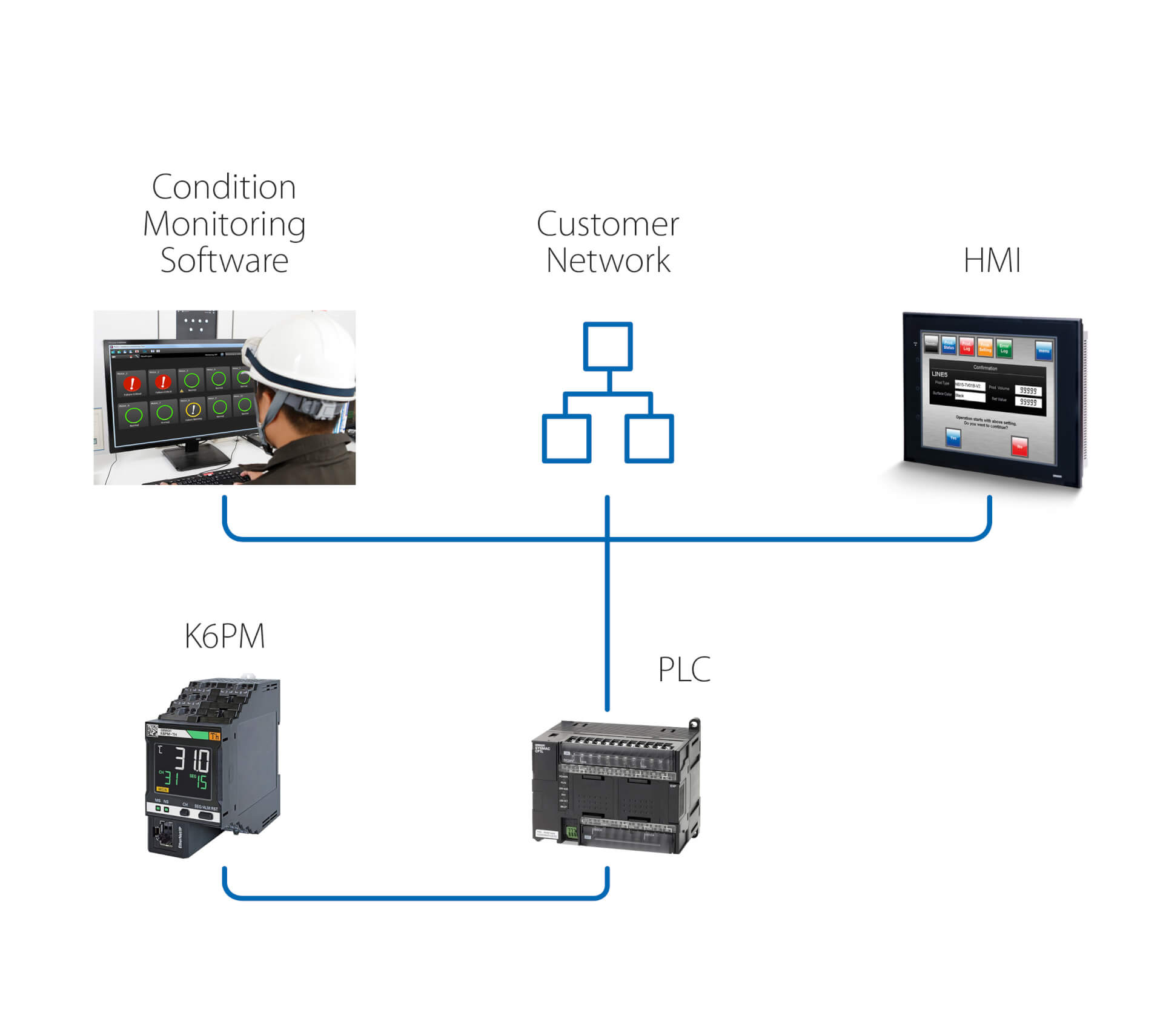
Instalação autónoma (com PLC)
Adicionalmente às características da solução anterior, esta solução permite:
- Monitorizar o estado do motor através do software de monitorização do estado, que funciona num PC ligado através de um PLC
- Utilizar a ligação remota do PLC para aceder ao K6PM para configuração e monitorização remotas
- Ativar ações através do PLC, após qualquer aviso/alarme detectado pelo K6PM
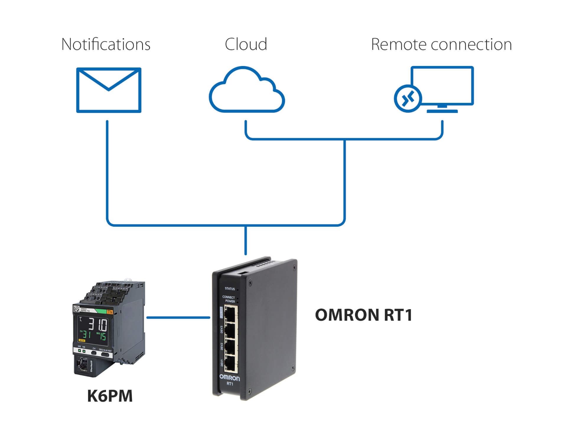
Notificações e monitorização remota – sem PLC
Esta solução, utilizando o OMRON RT1 como gateway, permite:
- notificações por e-mail/SMS no caso de serem detetadas anomalias pelo K6PM
- ligação segura (gerida pelo RT1) à nuvem, através da rede LAN ou através de uma ligação 4G
- ligação segura para monitorização remota e configuração do K6PM, utilizando o software de monitorização do estado fornecido com o controlador
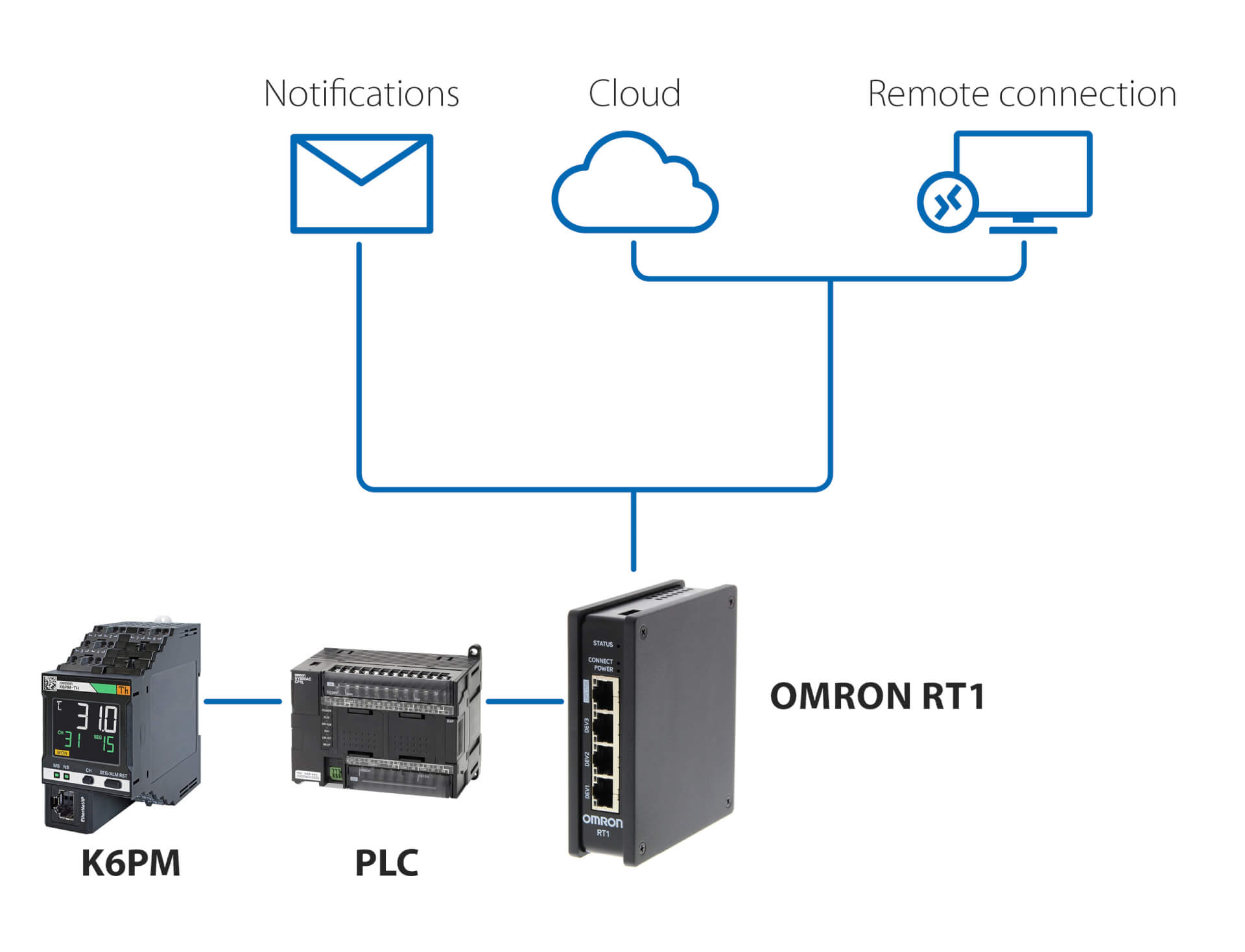
Notificações e monitorização remota – com PLC
Esta solução, utilizando qualquer PLC e o OMRON RT1 como gateway, permite:
- notificações por e-mail/SMS no caso de serem detetadas anomalias pelo K6PM
- ligação segura (gerida pelo RT1) à nuvem, através da rede LAN ou através de uma ligação 4G
- ligação segura para monitorização remota e configuração do K6PM, utilizando o software de monitorização do estado fornecido com o controlador
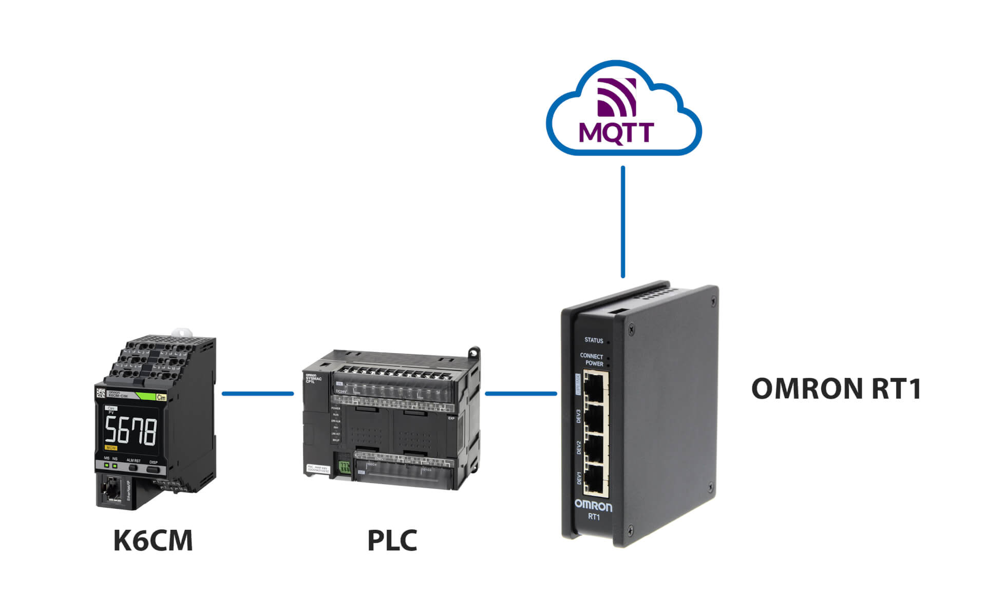
Ligação ao servidor MQTT
Produtos relacionados
-
Dispositivo de monitorização do estado do motor – Monitorização da corrente
-
Dispositivo de monitorização do estado do motor – Monitorização do isolamento
-
Dispositivo de monitorização do estado do motor – Monitorização da vibração
-
Dispositivo de monitorização do estado – Monitorização do isolamento
Downloads